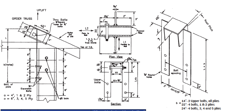
Uplift Strap Connector NVUCD
3/4″ Power Fasteners Wedge Bolts
2000 PSI Grout Filled Concrete Masonry Wall
|
PRODUCT
CODE |
PLYS
|
XX
(IN) |
Allowable Uplift Loads (lbs) |
Allowable Lateral Loads (lbs)
L1 &L2 |
||
|
2 Upper Bolts
|
4 Bolts
|
2 Upper Bolts
|
4 Bolts
|
|||
|
NVUCD-1
|
1
|
2
|
2800
|
4800
|
2100
|
2770
|
|
NVUCD-2
|
2
|
4
|
3750
|
7500
|
2800
|
4900
|
|
NVUCD-3
|
3
|
6
|
4665
|
9330
|
3500
|
5200
|
|
NVUCD-4
|
4
|
7
|
4665
|
9330
|
3500
|
5200
|
|
NVUCD-5
|
5
|
8 ½”
|
4665
|
9330
|
3500
|
5200
|
|
Roof Slope |
Vlaues of L (in)
|
|
|
Rafter 2X4
|
Rafter 2X6
|
|
|
3/12
|
5.6
|
7.7
|
|
4/12
|
6.4
|
8.5
|
|
5/12
|
7.1
|
9.3
|
|
6/12
|
7.9
|
10.2
|
|
7/12
|
8.7
|
11.0
|
|
8/12
|
9.5
|
11.9
|
Structural Notes:
1) Design conforms to FBC 2007, IBC 2006 and NDS 2005.
2) 3/16″ thick Structural steel shall conform to ASTM A36, yield strength 36000 psi.
Load Value Shown are based on Steel Stress without 33% increase.
3) All welding shall be minimum 3/16″ with E70 electrodes and shall conform to latest AISC/AWS codes. All contact areas shall be fully fillet welded.
4) All 3/4″ diameter bolts though wood shall be per ANSI/ASME Standard B18.2.1.
5) The Later loads shall not exceed the Truss Chord Capacity.
6) Lateral Loads combined with uplift loads, shall satisfy the following equation:
![]() 7) All Power Fasteners wedge bolt anchors shall be per Power Fasteners Catalog. Minimum anchor embedment shall be 5″. Minimum normal weight concrete shall be 2000 psi. Anchor diameter is 3/4″. Bolt Values are without 33% increase.
7) All Power Fasteners wedge bolt anchors shall be per Power Fasteners Catalog. Minimum anchor embedment shall be 5″. Minimum normal weight concrete shall be 2000 psi. Anchor diameter is 3/4″. Bolt Values are without 33% increase.
8) Uplift and Lateral values shown are reduced for bolt spacing and edge distance per Power Fasteners Catalog. Uplift loads shall not exceed Truss Chord capacity.
9) Uplift values are also controlled by compression perpendicular to grain of 565 psi for Southern Pine per NDS-2005. For other species, contact Engineer for values.
10) Provide plywood shims to close the gap between truss chords to obtain full bearing and prevent bending of thru bolts.
11) All products are painted Royal Blue for easy identification.
12) Concrete masonry Shall be ASTMC90, F’m= 1500 psi or greater. All Cells with Power Fasteners Shall be grut filled.