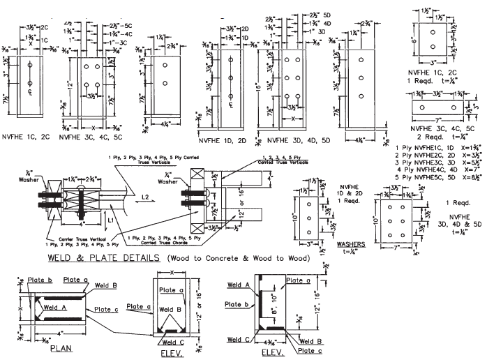
Wood to Wood Truss Hangers NVFHE
| Carrier Truss Verticals | ALLOWABLE LOADS (lbs.) | ||||||||
|---|---|---|---|---|---|---|---|---|---|
| Carried Truss | 12″ HIGH | 16″ HIGH | |||||||
| 1 Ply NVFHE1C | 2 Ply NVFHE2C | 3 Ply NVFHE3C | 4 & 5 Ply NVFHE4C, 5C |
1 Ply NVFHE1D | 2 Ply NVFHE2D | 3 Ply NVFHE3D | 4 & 5 Ply NVFHE4D, 5D |
||
| 1 PLY 1-2×6 |
Gravity | 2510 | 2510 | 5200 | 5200 | 4360 | 4360 | 8860 | 8860 |
| Uplift | 3520 | 3520 | 7380 | 7380 | 6510 | 6510 | 13350 | 13350 | |
| 2 PLY 2- 2×6 |
Gravity | 3755 | 3755 | 7288 | 7288 | 7070 | 7070 | 10372 | 10372 |
| Uplift | 4960 | 4960 | 9870 | 9870 | 7890 | 10150 | 14805 | 14805 | |
| 3 PLY 3- 2×6 |
Gravity | 3900 | 3900 | 7288 | 7288 | 7410 | 7410 | 10372 | 10372 |
| Uplift | 5110 | 5110 | 9870 | 9870 | 7890 | 1580 | 14805 | 14805 | |
| 4 & 5 PLY 4- 2×8 5-2×8 |
Gravity | 3900 | 3900 | 7288 | 7288 | 7410 | 7410 | 10372 | 10372 |
| Uplift | 5100 | 5100 | 9870 | 9870 | 7890 | 10580 | 14805 | 14805 | |
NVFHE1C, NVFHE2C, NVFHE3C & NVFHE4C & NVFHE5C-12” high
NVFHE1D, NVFHE2D, NVFHE3D & NVFHE4D & NVFHE5D-16” high.
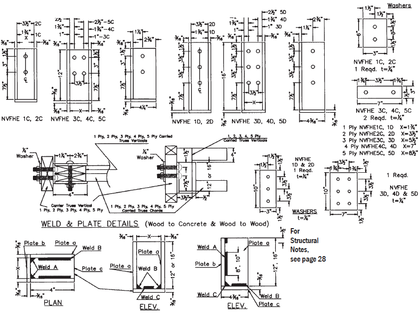
Weld A: 8” long for 12” high & 10” long for 16” high plates and 1/2” at top.
Weld B: Continuous 3/16″ Fillet.
Weld C: Continuous 3/16″ Fillet.
Plates a: 4″ x 3/16″ x 12″ or 16″
Plate b: (X+½”) x 3/16” x 12” or 16”
Plate c: (X+½”) x 3/16” x 4 3/16”
|
NVFHE
|
Carried Truss Verticals
|
|---|---|
|
1C, 1D
|
2 x 4
|
|
2C, 2D
|
2 x 6
|
|
3C, 3D
|
2 x 8
|
|
4C, 4D
|
2 x 8
|
|
5C, 5D
|
2 x 8
|
Structural Notes: Wood to concrete and Wood to Wood connectors
1. All designs conforms to 2006/2007 FBC and 2006 IBC and IRC and NDS 2005.
2. 3/16″ thick structural steel shall conform to ASTM A36 yield strength 36000psi. All Bolt holes are 13/16″ diameter.
3. All welding shall be minimum 3/16″ with E70 electrodes and shall conform to latest AISC/AWS codes. All welds shall be fillet welds.
4. All power fasteners wedge bolt anchors shall be manufacturer’s published information. Minimum anchor diameter is 3/4″ and anchor embedment shall be 6″.
5. Uplift values in concrete shown are reduced for bolt spacing and edge distance. Power Fasteners are used without 33% increase in allowable values.
6. All bolt values in wood conform to NDS 2005 for southern pine, G=0.55. Values for other species shall be adjusted as per NDS 2005.
7. Bolts shall not penetrate Truss top and bottom cords and shall only be through Truss Verticals. Bolts thru wood shall conform to section 11.1,2 of NDS 2001 and table 11 G for shear values.
8. This connector shall only be used for wood members loaded parallel to grain.
9. Steel stress is not increased by 33%.
10. Provide plywood shims to close the gap between carried truss and steel connectors to prevent bending of bolts.
11. All products are painted Royal Blue for easy Identification.
|
Carried
Truss Verticals |
Allowable Lateral Loads (lbs.)
|
||||||||
|---|---|---|---|---|---|---|---|---|---|
|
Carried
Truss |
12″ High
|
16″ High
|
|||||||
|
1 Ply
NVFHE1C |
2 Ply
NVFHE2C |
3 Ply
NVFHE3C |
4 & 5 Ply
NVFHE4C, 5C |
1 Ply
NVFHE1D |
2 Ply
NVFHE2D |
3 Ply
NVFHE3D |
4 & 5 Ply
NVFHE4D, 5D |
||
|
1PLY
1 – 2×6 |
L1
|
510
|
865
|
1135
|
1730
|
765
|
1300
|
1700
|
2595
|
|
L2
|
890
|
1790
|
2390
|
2690
|
1330
|
2680
|
3580
|
4030
|
|
|
2 PLY |
L1
|
870
|
1340
|
1905
|
2675
|
1310
|
2010
|
2860
|
4015
|
|
L2
|
890
|
1790
|
2390
|
2690
|
1330
|
2680
|
3580
|
4030
|
|
|
3
PLY 3 – 2X8 |
L1
|
1055
|
1546
|
2295
|
3095
|
1585
|
2320
|
3440
|
4640
|
|
L2
|
890
|
1790
|
2390
|
2690
|
1330
|
2680
|
3580
|
4030
|
|
|
4 & 5 PLY |
L1
|
1136
|
1632
|
1866
|
3265
|
1705
|
2450
|
3690
|
4895
|
|
L2
|
890
|
1790
|
2390
|
2690
|
1330
|
2680
|
3580
|
4030
|
|
NVFHE1C, NVFHE2C, NVFHE3C, NVFHE4C & NVFHE5C-12″ High
NVFHE1D, NVFHE2D, NVFHE3D, NVFHE4D & NVFHE5D-16″ High
Weld A: 8″ long for 12″ high & 10″ long for 16″ high plates and 1/2″ at top.
Weld B: Continouous 3/16″ Fillet.
Weld C: Continuous 3/16″ Fillet.
Plates a: 4″ x 3/16″x 12″ or 16″
Plate b: (X+½”) x 3/16″ x 12″ or 16″
Plate c: (X+½”) x 3/16″ x 4 ¼”
|
NVFHE
|
Carried Truss Veritcals
|
|---|---|
|
1C, 1D
|
2 X 4
|
|
2C, 2D
|
2 X 6
|
|
3C, 3D
|
2 X 8
|
|
4C, 4D
|
2 X 8
|
|
5C, 5D
|
2 X 8
|
Structrual Notes: Wood to concrete and wood to wood connectors.
1) All design conforms to 2006/2007 FBC and 2006 IBC and IRC AND NDS 2005.
2) 3/16″ thick structural steel shall conform to ASTM A36, yield strength 36000 psi. All bolt holes are 13/16″ diameter.
3) All welding shall be minimum 3/16″ with E70 electrodes and shall conform to latest AISC/AWS codes. All welds shall be fillet welds.
4) All Power Fasteners wedge bolt anchors shall manufacturer’s published information. Minimum anchor diameter is 3/4″ and anchor embedment shall be 6″.
5) Lateral values in concrete shown are reduced for bolt spacing and edge distance. Power fasteners are used without 33% increase in allowable values.
6) All bolt values in wood conform to NDS 2001 for southern pine, G=0.55. Values for other species shall be adjusted as per NDS 2005. Bolts are 3/4″ diameter.
7) Bolts shall not penetrate Truss top and bottom chords and shall only be through Truss Verticals. Bolts thru wood shall conform to section 11.1.2 of NDS 2005 and table 11 G for shear values.
8) This connector shall only be used for wood members loaded parallel to grain.
9) Steel stress is not increased by 33%.
10) Provide plywood shims to close the gap between truss chords and steel connectors to prevent bending of bolts.
11) Lateral loads shall be combined with Uplift loads to satisfy the equation:
![]()
12) All products are painted Royal Blue for easy identification.